


CV Type Progressive Feeder
- Work with Resistance Lubricators
-
Suitable for Oil and Grease
-
CV progressive feeder can deliver a fixed volume of lubricant to each lubrication point. The standard discharge volume is 0.18cc per stroke. The outlets of the CV progressive feeder can be combined for a larger discharge volume on request.
- Each outlet of a CV progressive feeder has one piston inside. The lubricant flow moves each piston, and CV progressive feeder discharges lubricant one by one outlet to complete a circulation cycle.
- Forbid to plug any CV progressive feeder outlet, or it cannot discharge lubricant functionally.
- Each standard CV progressive feeder has an indicator pin that moves in and out once as a completed circulation cycle. Monitoring can be done visually or electronically with a sensor or proximity switch.
- There are two types of inlet and outlet adapters: compression bushings with sleeves and quick couplings. Please follow the instructions below to connect and disconnect a quick coupling.
◆ Instructions on How to Connect and Disconnect a Quick Coupling.
| Connecting Pipe witch Quick Coupling | Disconnecting Pipe with Quick Coupling | ||
|
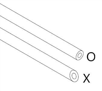
1. Make sure the cutting edge of the pipe is smooth and flat. |
|
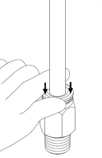
1. Push down the top of the quick coupling with the thumb and index finger to loosen it from the pipe. |
|
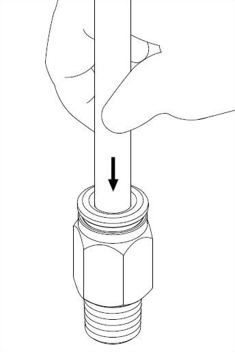
2. Insert the pipe into the quick coupling then you will hear two click sounds. |
|
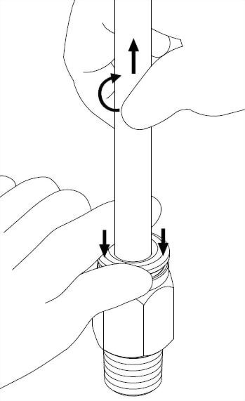
2. Use the other hand to push the pipe into the quick coupling gently. Then,rotate the pipe for approximately a 90-degree angle and simultaneously pull the pipe out. |
| 3. Pull the pipe to check if it is securely locked. | |||
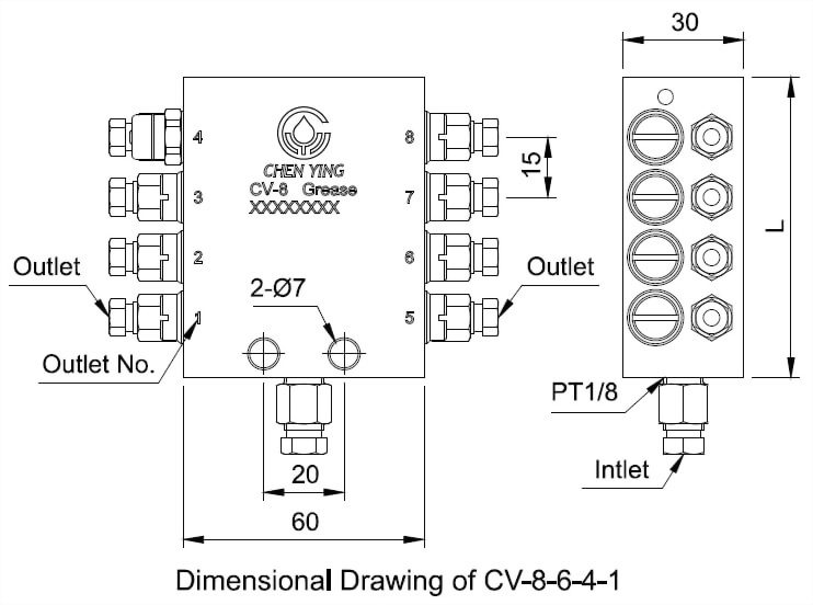
◆ Dimensional Data
| Model | Outlet Num. | Inlet Bore | Outlet Bore | L(mm) | N.W.(g) |
| CV-6 | 6 |
Ø6 (M10xP1.0)
or
Ø8 (M14xP1.5)
|
Ø4 (M8xP1.0)
or
Ø6 (M10xP1.0)
|
60 | 407 |
| CV-8 | 8 | 75 | 514 | ||
| CV-10 | 10 | 90 | 628 | ||
| CV-12 | 12 | 105 | 686 | ||
| CV-14 | 14 | 120 | 840 | ||
| CV-16 | 16 | 135 | 937 | ||
| CV-18 | 18 | 150 | 1062 | ||
| CV-20 | 20 | 165 | 1169 |
◆ Technical Data
Suitable Lubricant
Suitable Viscosity
Operating Pressure Range
Discharge Volume
Suitable Lubricators
Oil
32~220 cst@40℃
5~30kgf/cm2
About 0.18cc/Stroke
Resistance Type Oil Lubricators with Discharge Volume Above 500cc/min
Grease
NLGI 000~2
15~150kgf/cm2
About 0.18cc/Stroke
Resistance Type Grease Lubricators
◆ Order Code
Model
Inlet
Bore
Outlet
Bore
Lubricant
Special
Request
CV-6
6
4
1
※
CV-8
6
Ø6
4
Ø4
0
Oil
A
Add a Sensor
Switch (for Grease CV Only)
CV-10
8
Ø8
6
Ø6
1
Grease
B
Add a Proximity
Switch (for Oil CV Only)
CV-12
6Q
Ø6 Quick Coupling
4Q
Ø4 Quick Coupling
CV-14
6Q
Ø6 Quick Coupling
CV-16
CV-18
CV-20
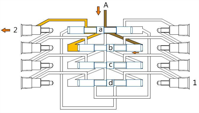
◆ How CV Progressive Feeder Works (Take CV-8 as an example)

1. The
lubricant pressure forces the lubricant to flow into inlet
"A",fills up each piston hole with lubricant, and pushes pistons to
move to each tap stop.
2. Piston "a" moves to
the left that makes the lubricant changing the flow direction. The
original lubricant of the left side piston "a" flows through piston
"d" and keeps moving to the first outlets.
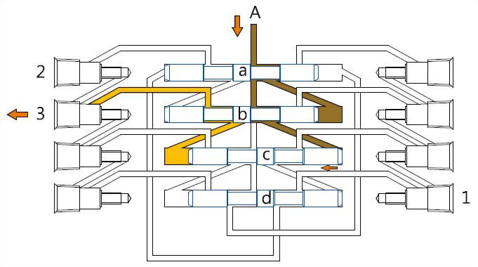
3. After the flow
direction is changed, the lubricant moves toward piston "b" which
forces piston "b" to move toward the left. The original lubricant
of the left side piston "b" flows through piston "a",and
keeps moving to the second outlet.
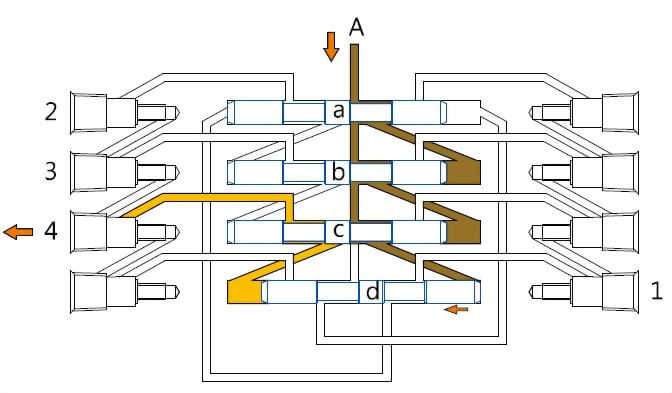
4. After the flow
direction is changed, the lubricant moves toward piston "c" which
forces piston "c" to move toward the left.The original lubricant of
the left side piston "c" flows through piston "b",and
keeps moving to the third outlet.
5. After the flow
direction is changed, the lubricant moves toward piston "d" which
forces piston "d" to move toward the left. The original lubricant
of the left side piston "d" flows through piston "c", and
keeps moving to the fourth outlet.

6. After the flow
direction is changed, the lubricant moves toward piston "a" which
forces piston "a" to move toward the left. The original lubricant
of the right side piston "a" flows through piston "d" ,
and keeps moving to the fifth outlet. The left side circulation is completed.
7. The right-side circulation is the same as the left-side circulation.