

POA Oil-Air Type Pneumatic Lubricator
- Metered Qil Quantity
-
Automatic Lubrication Controlled by PLC
- The operation and interval time of POA are controlled by PLC.
- POA is actuated by pneumatic and controlled by a solenoid valve, which could be an ON/OFF switch. The input pneumatic pressure determines the output pressure. Oil discharges during operation.
- Recommend using input pneumatic pressure of 3.5~7 kgf/cm2 and setting up a solenoid valve's ON/OFF time of more than 5 seconds for discharging oil.
- POA has a feed-oil button which can be used for manual oil feeding.
- Recommend working with OC type oil-air volume distributors to deliver the metered quantity of oil-air mixture to lubrication points.
- POA has two pressure gauges that enable the user to check the input pneumatic and output operating pressure easily.
- POA has a NC contact float switch that detects the oil level automatically and sends signals when the oil level is low.
- POA has three NC Contact socket pressure switches, and the specifications are as follows.(1) High Oil-Pressure Switch sets 20 kgf/cm2 to detect the operating pressure.(2) Low Oil-Pressure Switch sets 1 kgf/cm2 to detect the pressure-relief function.(3) Air-Pressure Switch sets 3.5 kgf/cm2 to detect the pneumatic pressure.
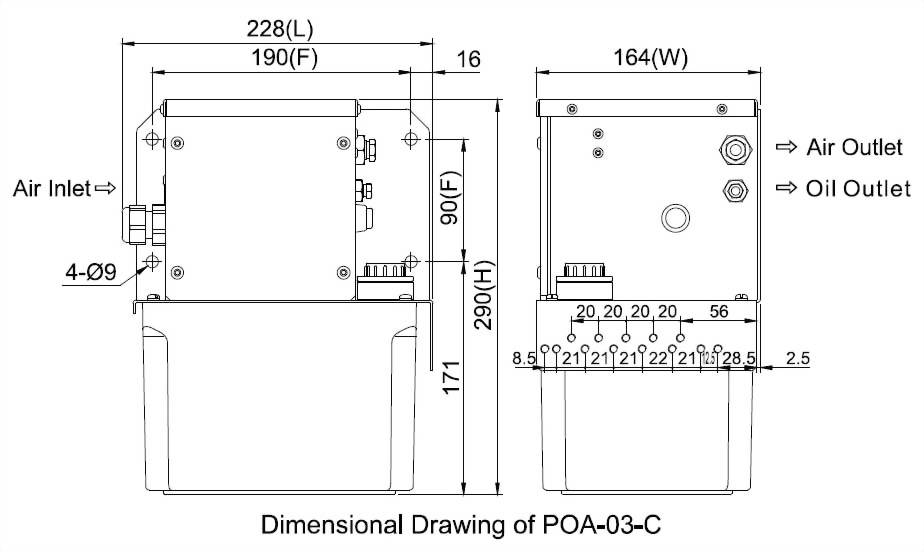
◆ Dimensional Data
Tank
Capacity
Tank Material
Length (mm)
Width (mm)
Height (mm)
Fixed Hole
Distance (mm)
N.W. (kg)
3L
Resin
228
164
290
90x190
5.50
◆ Technical Data
Voltage
AC110V,
AC220V, DC12V, DC24V
Pneumatic Pressure (kgf/c㎡)
3.5
4.0
4.5
5.0
5.5
6.0
6.5
7.0
Operating Pressure (kgf/c㎡)
26
30
34
38
41
45
49
53
Discharge Volume
5cc/stroke
Air Inlet
PT3/4
Air Outlet
Ø8
Oil Outlet
Ø6
Float Switch
NC
Contact (NO Contact on request)
Pressure Switch
NC
Contact (NO Contact on request)
Suitable Viscosity
Oil, 10-68 cSt@40oC
◆ Wiring Diagram
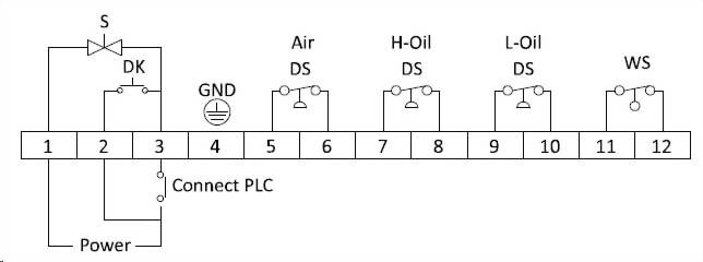
GND = Ground
DS = Pressure Switch
WS = Float Switch
DK = Feed-Oil Button
S = Solenoid Valve
◆ Order Code
Model
Tank Capacity (Material)
Volage
Special Request
POA
03
C
※
03
3L (Resin)
A
AC 110V
AO
NO Contact Air
Pressure Switch
C
AC 220V
HO
NO Contact High
Oil-Pressure Switch
J
DC 12V
LO
NO Contact Low
Oil-Pressure Switch
K
DC 24V
OC
SO
NO Contact Float
Switch
◆The dimensional and technical data of OC Type Oil-Air Volume Distributor is as described below.
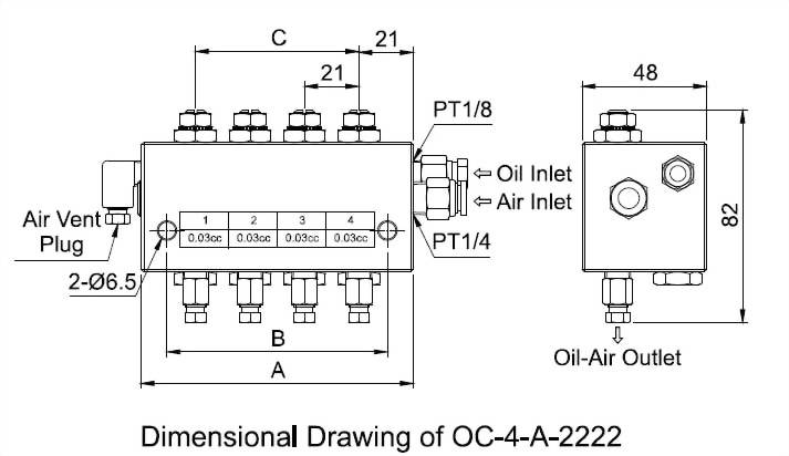
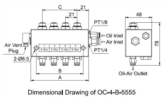
◆ Dimensional Data & Technical Data
| Model | Outlet Num. | Air Inlet Bore | Oil Inlet Bore | Oil-Air Outlet Bore | A(mm) | B(mm) | C(mm) |
Discharge Volume Per Stroke |
Operating Oil Pressure Range |
Operating Air Pressure Range |
Suitable Viscosity | N.W.(g) | |
| Standard Type | Quick Coupling Type | ||||||||||||
| OC-2 | 2 | Ø8xPT1/4 | Ø6(M10xP1.0) | Ø4(M8xP1.0) | 63 | 43 | 21 |
0.01cc
0.03cc
0.06cc
0.10cc
0.16cc
|
20-30kgf/cm2 | 3.5-7kgf/cm2 | 10-68 cSt@40 | 527 | 523 |
| OC-3 | 3 | 84 | 64 | 42 | 706 | 700 | |||||||
| OC-4 | 4 | 105 | 85 | 63 | 884 | 874 | |||||||
| OC-5 | 5 | 126 | 106 | 84 | 1064 | 1051 | |||||||
| OC-6 | 6 | 147 | 127 | 105 | 1241 | 1229 | |||||||
◆ Order Code
Model
Outlet Number
Oil lnlet &
Oil-Ail Outlet Adapter Type
Discharge Volume
OC
4
A
1-1-1-1
2
2
A
Compression Bushing & Compression Sleeve
1
0.01cc
3
3
B
Quick Coupling
2
0.03cc
4
4
3
0.06cc
5
5
4
0.10cc
6
6
5
0.16cc
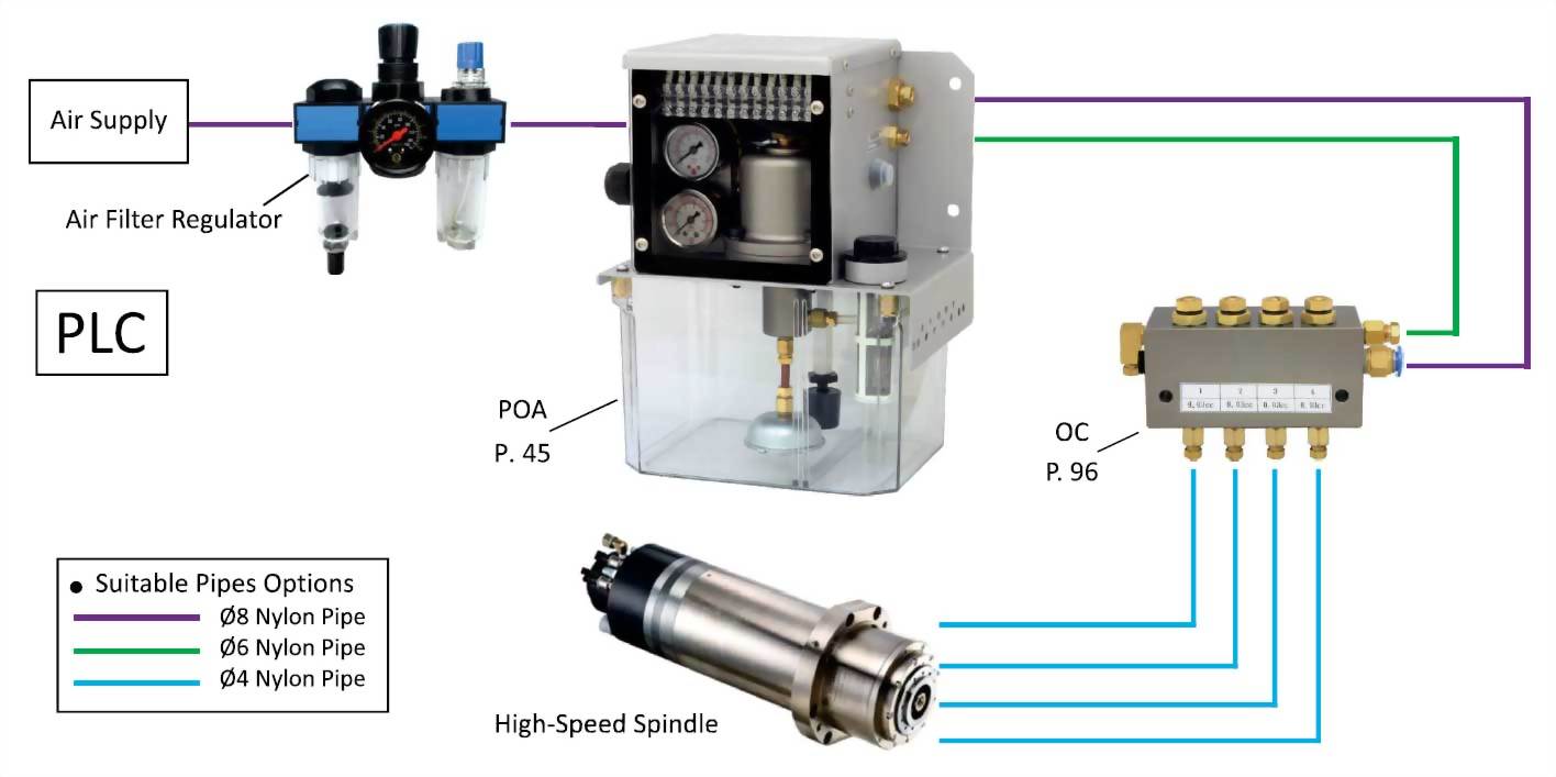
◆ POA Lubricator and OC Distributor Oil-Air Lubrication System Layout
")


")


")