

CEF Circulating Type Oil Electric Lubricator
- Proportional Oil Quantity
-
Automatic Lubrication Controlled by Timer
- CEF has a cyclic inlet that allows the oil to return to the oil tank, which saves the oil consumption.
- CEF has a magnetic filter inside the cyclic inlet that prevents iron filings from flowing into the oil tank to maintain the cleanness of the circulating oil.
- CEF has a timer that controls its operation and interval time. The control box has four indicators, operation (ACT), alarm (ALM), immediate lubrication (RUN), and interval (INT).
- The control box has a build-in buzzer that sends an alarm sound when the oil level is low.
- The gear pump of CEF is made of special aluminum alloy and assembled with the induction motor to provide stable output pressure, low operating noise, and long service life.
- CEF has a pressure-regulating valve that enables the user to adjust the operating pressure.
- CEF has a NC contact float switch that detects the oil level automatically and sends signals when the oil level is low.
- CEF has a feed-oil button (F button), which can be used as manual oil feeding for less than 3 minutes to avoid overloading the motor.
-
After installing CEF and connecting all oil pipes, let CEF continue running until oil fulfills all oil pipes. The lubricator is ready to use when the oil flows out to remove the air bubbles.
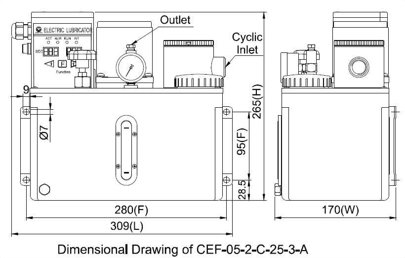
◆ Dimensional Data
Motor
Power
Tank Capacity
Tank Material
Length (mm)
Width (mm)
Height (mm)
Fixed Hole
Distance (mm)
N.W. (kg)
25W
4L
Aluminum
309
170
265
95x280
7.50
8L
Iron
355
201
283
95x338
10.10
12L
Iron
495
225
265
95x478
12.40
60W
8L
Iron
355
201
333
95x338
11.15
12L
Iron
495
225
311
95x478
13.45
◆ Technical Data
Operation
Time
1-999
sec
Interval Time
1-999
sec, 1-999 min
Motor Power
25W
60W
Voltage
110V
220V
110V
220V
Ampere
0.6A
0.3A
1.2A
0.6A
Max. Discharge Volume
250cc/min
500cc/min
Max. Operating Pressure
15kgf/c㎡
30kgf/c㎡
Hertz
50/60Hz Compatible
Discharge Bore
Ø4, Ø6
Cyclic Inlet
PT1/2, PT3/4
Float Switch
NC Contact
Suitable Viscosity
Oil, 32-68 cSt@40℃
◆ Wiring Diagram
Abnormal
Output
Ground
Power
NO(A)
NC(B)
COM
GND(P.E)
POWER
⊕
⊕
⊕
⊕
⊕
⊕
◆ Order Code
Model
Tank
Capacity(Material)
ACT x
INT
Voltage
Motor Power
Discharge Bore
Cyclic
Inlet
CEF
05
2
C
25
3
A
05
4L
(Alum.)
1
sec x sec
A
110V
25
25W
0
Ø4
A
PT1/2
08
8L
(Iron)
2
sec x min
C
220V
60
60W
(Available for 8L metal tank and above only)
1
Ø6
B
PT3/4
12
12L
(Iron)
90
90W
(Available for 8L metal tank and above only)
2
Ø4
W/Pressure Gauge
20
20L
(Iron)
3
Ø6
W/Pressure Gauge
30
30L
(Iron)
36
36L
(Iron)
40
40L
(Iron)
60
60L
(Iron)
64
64L
(Iron)
77
77L
(Iron)

")

")
")

")

")
")

")


")