

CEH Circulating Type Oil Electric Lubricator
- Proportional Oil Quantity
-
Automatic Lubrication Controlled by PLC
- CEH has a cyclic inlet that allows the oil to return to the oil tank, which saves the oil consumption.
- CEH has a magnetic filter inside the cyclic inlet that prevents iron filings from entering the oil tank to maintain the cleanness of the circulating oil.
- The operation and interval time of CEH are controlled by PLC. CEH also can operate continuously without interval time.
- The gear pump of CEH is made of special aluminum alloy and assembled with the induction motor to provide stable output pressure, low operating noise, and long service life.
- CEH has a pressure-regulating valve that enables the user to adjust the operating pressure.
- CEH has a NC float switch that detects the oil level automatically and sends signals when the oil is level is low.
-
After installing CEH and connecting all oil pipes, let CEH continue running until oil fulfills all oil pipes. The lubricator is ready to use when the oil flows out to remove the air bubbles.
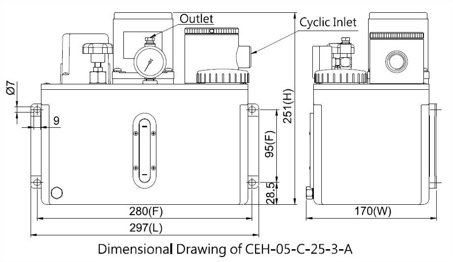
◆ Dimensional Data
Motor
Power
Tank Capacity
Tank Material
Length (mm)
Width (mm)
Height (mm)
Fixed Hole
Distance (mm)
N.W. (kg)
25W
4L
Aluminum
297
170
251
95x280
6.85
8L
Iron
355
201
271
95x338
9.85
12L
Iron
495
225
251
95x478
12.60
60W
8L
Iron
355
201
333
95x338
11.35
12L
Iron
495
225
311
95x478
13.65
◆ Technical Data
Motor
Power
25W
60W
Voltage
1Ø110V
1Ø220V
Three Phase
1Ø110V
1Ø220V
Three
Phase
Ampere
0.6A
0.3A
0.3A
1.2A
0.6A
0.6A
Max. Discharge Volume
250cc/min
500cc/min
Max. Operating Pressure
15kgf/c㎡
30kgf/c㎡
Hertz
50/60Hz
Compatible
Discharge Bore
Ø4 ,
Ø6
Cyclic Inlet
PT1/2,
PT3/4
Float Switch
NC
Contact (NO Contact on request)
Suitable Viscosity
Oil, 32-68 cSt@40℃
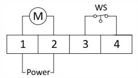
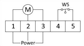
◆ Wiring Diagram
※The motor shaft is marked with a red dot. When wiring the three-phase-voltage CEH, please note the motor should rotate anticlockwise. If the motor rotates clockwise, please switch the position of any two of the power wires and rewire them.
Single-Phase
Power
Three-Phase
Power
M =
Motor
WS =
Float Switch
◆ Order Code
Model
Tank
Capacity(Material)
Voltage
Motor Power
Discharge Bore
Cyclic Inlet
Special
Request
CEH
05
C
25
3
A
※
05
4L
(Alum.)
A
1Ø110V
25
25W
0
Ø4
A
PT1/2
SO
NO
Contact Float Switch
08
8L
(Iron)
C
1Ø220V
60
60W
(Available for 8L metal tank and above only)
1
Ø6
B
PT3/4
12
12L
(Iron)
D
3Ø220/380V
90
90W
(Available for 8L metal tank and above only)
2
Ø4 W/Pressure Gauge
20
20L
(Iron)
E
3Ø220/440V
3
Ø6 W/Pressure Gauge
30
30L
(Iron)
F
3Ø208/415V
36
36L
(Iron)
G
3Ø230/460V
40
40L
(Iron)
H
3Ø240/480V
60
60L
(Iron)
M
3Ø220V
64
64L
(Iron)
N
3Ø380V
77
77L
(Iron)
X
Special Voltage
※A standard dual-voltage motor is connected for low voltage. Please specify if you need it to be connected for high voltage when placing an order.

")


")