

CESMB Resistance Type Oil Electric Lubricator
- Adjustable Oil Quantity
-
Fixed Interval Time
- The interval time of CES series lubricators is controlled by the rotational speed of the small synchronous motor that no external controllers or timers are needed.
- The discharge volume of CES series lubricators is adjustable.
- CESMB and CESSB have NO contact float switches that detect the oil levels automatically and send signals when the oil levels are high.
- CESC have a NC contact float switch that detects the oil level automatically and sends signals when the oil level is low.
- The control box of CESC has three indicators that show power, action, and alarm.
- A power indicator can be added to CESMA and CESMB on request to show when the power is on.
- A CE certified connector can be added to CESSB on request to change the wiring method from external to internal.
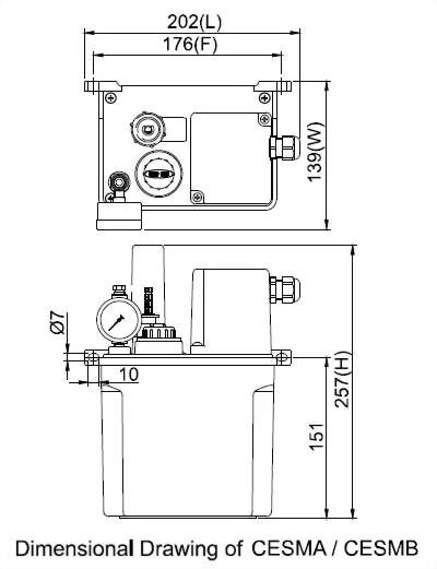
◆ Dimensional and Equipment Data
Tank Capacity
Length (mm)
Width (mm)
Height (mm)
Fixed Hole
Distance (mm)
N.W. (kg)
Float Switch
Buzzer
Pressure Gauge
Control Box
Indicator Light
Wiring Method
2L
202
139
257
176
1.86
O
X
O
X
Optional
Internal
◆ Technical Data
Interval
Time
2, 3,
5, 10, 15, 30, 60 min (Non-Adjustable)
Motor Power
4W
Voltage
110V
220V
Ampere
0.10A
0.05A
Hertz
50/60Hz Compatible
Max. Discharge Volume
3-6cc
Adjustable or 1-6cc Adjustable
Max. Operating Pressure
3kgf/c㎡
Discharge Bore
Ø4 ,
Ø6
Float Switch
NO
Contact (NC Contact on request)
Suitable Viscosity
Oil, 32-68 cSt@40oC
◆ Wiring Diagram
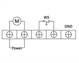
M = Motor
WS =Float Switch
◆ Order Code
Model
Interval
Time
Voltage
Discharge Volume
Discharge Bore
Special Request
CESMB
10
C
6
3
※
02
2 min
A
110V
1
1-6cc Adjustable
0
Ø4
L
Add
a Power Indicator Light
03
3 min
C
220V
6
3-6cc Adjustable
1
Ø6
SC
NC Contact Float Switch
05
5 min
2
Ø4 W/Pressure Gauge
10
10 min
3
Ø6 W/Pressure Gauge
15
15 min
30
30 min
60
60 min
")

")
")

")
")
")
")
")

")
")

")


")