


CEV Resistance Type Oil Electric Lubricator
- Proportional Oil Quantity
-
Automatic Lubrication Controlled by PLC
CEV-The Resistance Type Oil Electric Lubricator (Model CEV) is an advanced PLC-controlled device that offers efficient and reliable operation. Its pressure gauge allows for easy monitoring of operating pressure, while an NC contact float switch continuously monitors oil level and transmits a warning signal when oil level is low, effectively preventing insufficient lubrication and potential machine damage. A pressure-regulating valve enables precise adjustment of operating pressure. The gear pump, constructed from special aluminum alloy and coupled with an induction motor, delivers stable output pressure, low noise, and enhances durability. For added functionality, CEV models with 3L or larger oil tanks can be optionally equipped with a 1kgf/cm2 socket pressure switch for automatic pressure detection, a feed-oil button for manual lubrication, and an indicator light to signal oil discharge.
- The operation and interval time of CEV are controlled by PLC.
- CEV has a pressure gauge that enables the user to check the operating pressure easily.
- CEV has a NC contact float switch that detects the oil level automatically and sends signals when the oil level is low.
- CEV has a pressure-regulating valve that enables the user to adjust the operating pressure.
- The gear pump of CEV is made of special aluminum alloy and assembled with the induction motor to provide stable output pressure, low operating noise, and long service life.
-
The CEV with 3L and above oil tank can be added with the following parts on request.
● A 1kgf/cm2 socket pressure switch that detects the operating pressure automatically.
● A feed-oil button can be used for manual oil feeding.
● An indicator light that shows when CEV discharges oil.
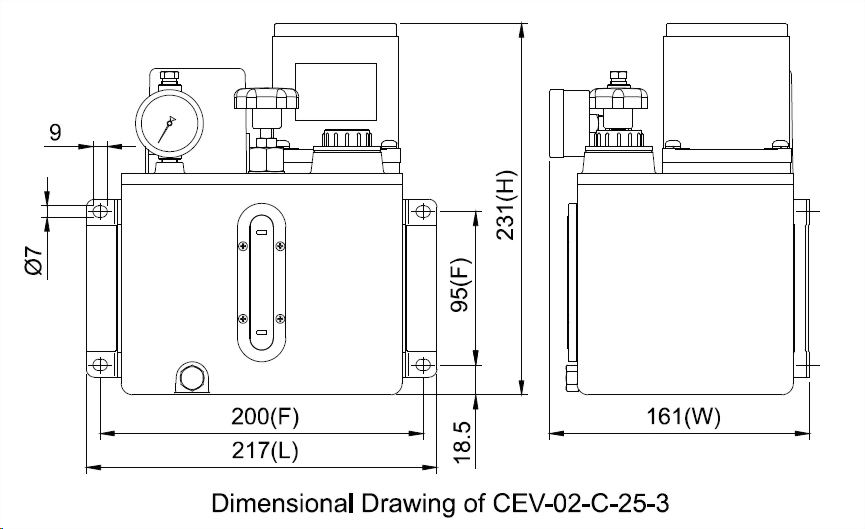
◆ Dimensional Data
| Motor Power | Tank Capacity | Tank Material | Length (mm) | Width (mm) | Height (mm) | Fixed Hole Distance (mm) | N.W. (kg) |
| 25W | 2L | Aluminum | 217 | 161 | 231 | 90x200 | 5.50 |
| 3L | Resin | 230 | 165 | 242 | 205 | 4.65 | |
| 4L | Resin | 275 | 159 | 252 | 250 | 5.00 | |
| 4L | Aluminum | 297 | 170 | 251 | 95x280 | 5.85 | |
| 8L | Iron | 355 | 201 | 271 | 95x338 | 9.00 | |
| 60W | 4L | Aluminum | 297 | 175 | 311 | 95x280 | 7.45 |
| 8L | Iron | 355 | 201 | 331 | 95x338 | 10.20 |
◆ Technical Data
| Motor Power | 25W | 60W | ||||
| Voltage | 1Ø110V | 1Ø220V | Three Phase | 1Ø110V | 1Ø220V | Three Phase |
| Ampere | 0.6A | 0.3A | 0.3A | 1.2A | 0.6A | 0.6A |
| Max. Discharge Volume | 250cc/min | 500cc/min | ||||
| Max. Operating Pressure | 15kgf/c㎡ | 30kgf/c㎡ | ||||
| Hertz | 50/60Hz Compatible | |||||
| Discharge Bore | Ø4 , Ø6 | |||||
| Float Switch | NC Contact (NO Contact on request) | |||||
| Pressure Switch | Optional (NC or No Contact) | |||||
| Suitable Viscosity | Oil, 32-68 cSt@40℃ | |||||
◆ Order Code
| Model | Tank Capacity (Material) | Voltage | Motor Power | Discharge Bore | Special Request | |||||
| CEV | 02 | C | 25 | 3 | ※ | |||||
|
|
02 | 2L (Alum.) | A | 1Ø110V | 25 | 25W | 0 | Ø4 | F | Add a Feed-Oil Button |
| 03 | 3L (Resin) | C | 1Ø220V | 60 | 60W (Available for 4L metal tank and above only) | 1 | Ø6 | L | Add a Power Indicator Light | |
| 04 | 4L (Resin) | D | 3Ø220/380V | 90 | 90W (Available for 4L metal tank and above only) | 2 | Ø4 W/Pressure Gauge | PC | Add a NC Contact Pressure Switch | |
| 05 | 4L (Alum.) | E | 3Ø220/440V | 3 | Ø6 W/Pressure Gauge | PO | Add a NO Contact Pressure Switch | |||
| 08 | 8L (Iron) | F | 3Ø208/415V | SO | NO Contact Float Switch | |||||
| 20 | 20L (Iron) | G | 3Ø230/460V | |||||||
| H | 3Ø240/480V | |||||||||
| M | 3Ø220V | |||||||||
| N | 3Ø2380V | |||||||||
| X | Special Voltage | |||||||||
※A standard dual-voltage motor is connected for low voltage.Please specify if you need it to be connected for high voltage when placing an order.
※Special request codes F,L,PC, and PO are only available for the CEV with 3L and above oil tanks.
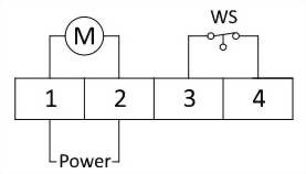
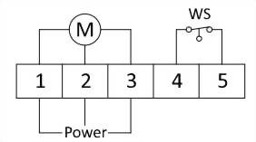
◆ Wiring Diagram
| Single-Phase Power | Three-Phase Power |
M = Motor
WS = Float Switch
|
|
|
|
※The motor shaft is marked with a red dot. When wiring the three-phase-voltage CEV, please note the motor should rotate anticlockwise. If the motor rotates clockwise, please switch the position of any two of the power wires and rewire them.

")

")
")

")

")
")

")


")