

MAG Resistance Type Grease Pneumatic Lubricator
- Proportional Grease Quantity
-
Pneumatic Lubrication
- The operation and interval time of MAG are controlled pneumatically.
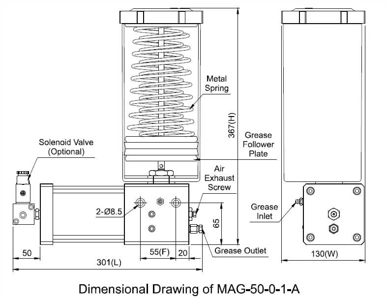
- A solenoid valve can be added as a switch for the pneumatic pressure supply to control the ON/OFF switch of MAG upon request.
- The operation time (ON) should be set up as 25 seconds, and the interval time (OFF) should be set up as 5 seconds to complete one operation cycle.
- MAG requires 4-8kgf/cm2 pneumatic pressure supply to have the corresponding 117-290kgf/cm2 operating pressure. It can meet different pressure requirements and applications.
- Please refill grease from the grease inlet to prevent air and impurities from entering the grease tank.
◆ Technical Data & Dimensional Data
Effective
Capacity
Length (mm)
Width (mm)
Height (mm)
Fixed Hole
Distance (mm)
Operation Time
Interval Time
Discharge
Volume
Grease Inlet
Air Inlet
Discharge Bore
Suitable
Viscosity
N.W.(kg)
1500cc
301
130
367
55
Over 25 sec.
Over 5 sec.
About
2.5cc/stroke
PT1/8
Grease Nipple
Ø8、Ø10
Ø4、Ø6、Ø8、Ø10
Grease
NLGI 000-2
6.53
◆ Pressure Chart (Reference Value)
Pneumatic
Pressure (kgf/c㎡)
4.0
4.5
5.0
5.5
6.0
6.5
7.0
7.5
8.0
Operating
Pressure (kgf/c㎡)
117
140
160
181
201
222
242
265
290
◆ Order Code
Model
Effectiv Capacity
Air
Inlet
Discharge Bore
Solenoid Valve
Special Request
MAG
50
0
1
0
※
50
1500cc
0
Ø8
0
Ø4 x PT1/4
0
Without a Solenoid Valve
G
Add a Pressure Gauge
1
Ø10
1
Ø6 x PT1/4
A
With a Solenoid Valve, AC110V
RC
Add a NC Contact
Magnetic Level Switch
2
Ø8 x PT1/4
C
With a Solenoid Valve, AC220V
RO
Add a NO Contact
Magnetic Level Switch
3
Ø10 x PT1/4
K
With a Solenoid Valve, DC24V


")


