

POM-AP Minimum Quantity Grease Pneumatic Lubricator
- Metered Grease Quantity
- Pneumatic Lubrication
-
Adjustable Grease Quantity
-
Grease Cartridge
-
Minimum Quantity Oil Lubricators Available for Selection
- The discharge volume of POM-A and POM-AP is precise and can be adjusted from 0.01cc to 0.08cc per stroke.
-
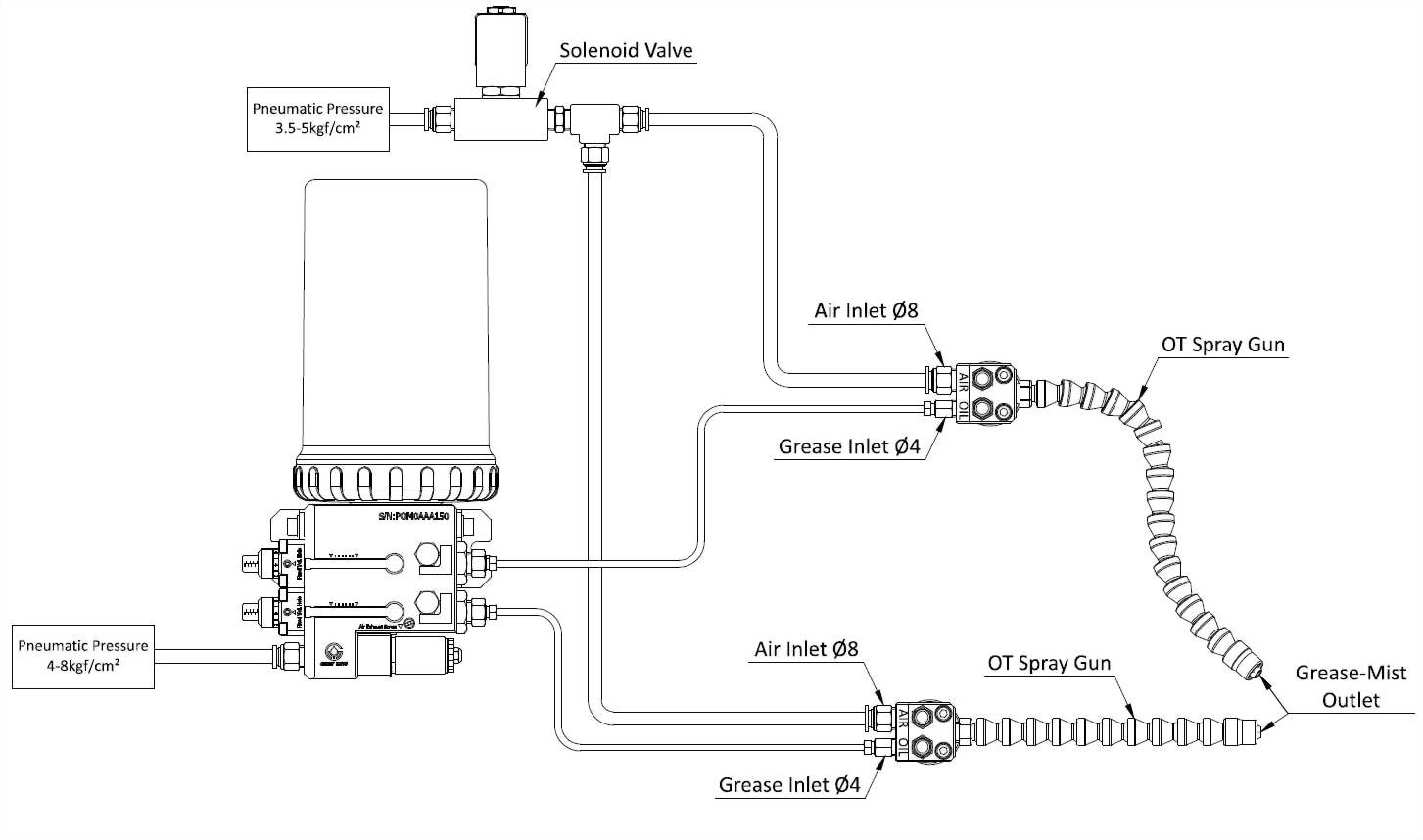
POM-A and POM-AP can be actuated either by a frequency generator or a solenoid valve.
● Pneumatic pressure supply drives the frequency generator, and the user can adjust each stroke frequency upon the demand. The service life is ten million cycles.
● The input voltage powers the solenoid valve, and the PLC can precisely control its stroke frequency. The solenoid valve works as the ON/OFF switch of the pneumatic pressure supply. The service life is two million cycles. - POM-A and POM-AP require 4-8kgf/cm2 pneumatic pressure supply to operate.
-
The standard POM-A and POM-AP have one outlet, which can be increased to two on request. Do not plug any outlet of POM-A and POM-AP.
- POM-A and POM-AP have grease volume adjusters for adjusting the discharge volume per stroke. It is fixed by the grease volume screw to prevent its setting from being changed easily.
- Each outlet of POM-A can add a reed switch for monitoring every stroke.
- A magnetic level switch can be added to POM-A and POM-AP on request to detect the grease level automatically.
- An OT spray gun with the φ4 inlet bore can work with either POM-A or POM-AP to have the grease mist effect.
- Please refill grease from the grease inlet to prevent air and impurities from entering the grease tank.
-
POM-AP-07 works with a 700cc disposable grease cartridge. When the grease is empty, replace POM-AP-07 with a new grease cartridge. Standard POM-AP-07 does not include a grease cartridge but is available upon request.
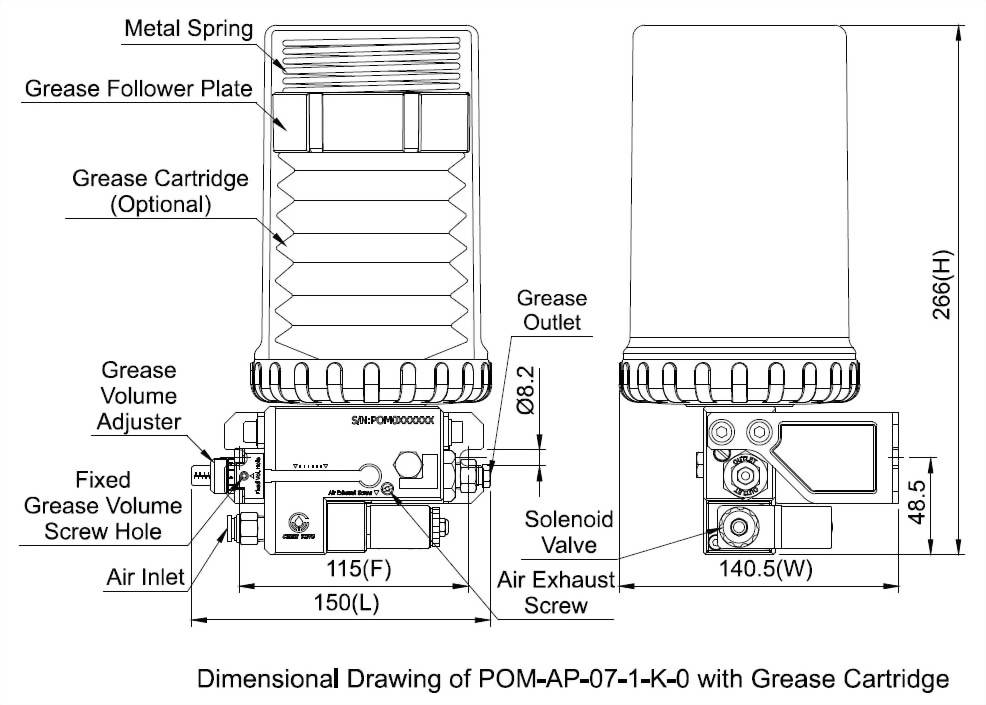
◆ Dimensional Data
Model
Effective
Capacity
Fixed Hole
Distance (mm)
Length (mm)
Width (mm)
Height (mm)
Outlet Number
N.W. (kg)
POM-AP-07
700cc
Grease Cartridge
115
150
140.5
266.0
1
1.82
294.5
2
2.23
POM-AP-40
550cc
115
150
125.0
304.5
1
1.94
330.0
2
2.35
POM-AP-50
1500cc
115
154
135.0
345.5
1
3.02
374.0
2
3.43
◆ Technical Data
Method
of Actuation
Solenoid
Valve
Frequency
Generator
Voltage
AC110V
AC220V
DC24V
--
Ampere
0.1A
0.1A
0.2A
--
Pneumatic Pressure
4-8kgf/cm²
Discharge Volume
0.01cc-0.08cc/stroke
(Adjustable)
Air Inlet Bore
Ø8
Discharge Bore
Ø4
Magnetic Level Switch
Optional
(NC or NO Contact)
Reed Switch
Optional (NC or NO Contact)
Suitable Viscosity
POM-AP-07:Grease,
NLGI 000-0
POM-AP-40, POM-AP-50:Grease, NLGI 1, 2
◆ Order Code
Model
Tank Capacity
Outlet
Number
Method of Actuation
Discharge Bore
Special Request
POM-AP
07
1
K
0
※
40
550cc
1
1 Outlet
1
Frequency Generator
0
Ø4
RC
Add a NC Contact
Magnetic Level Switch
50
1500cc
2
2 Outlets
A
Solenoid Valve,
AC110V
RO
Add a NO Contact
Magnetic Level Switch
07
700cc Grease
Cartridge
C
Solenoid Valve,
AC220V
TC
Add a NC Contact Reed
Switch
K
Solenoid Valve, DC24V
TO
Add a NO Contact Reed
Switch
※Please refer to the 700cc Grease Cartridge catalog if you need to purchase one.
◆ Minimum Quantity Grease Lubrication System Installation Schematic Diagram
◆ The dimensional and technical data of 700cc Grease Cartridge is as described below
◆ Order Code
| Order Code | Grease Type | Grease Viscosity | Minimum Order Quantity Requirement |
| I01D0021 | Mobilux EP023 | NLGI 000 | -- |
| I01D0012 | Mobil EP0 | NLGI 0 | -- |
| I01D0013 | Mobil EP1 | NLGI 1 | 100 |
| I01D0029 | Idemitsu Polylex UMF | NLGI 000 | 6 |
| I01D0030 | Idemitsu Eponex IM | NLGI 1 | 6 |
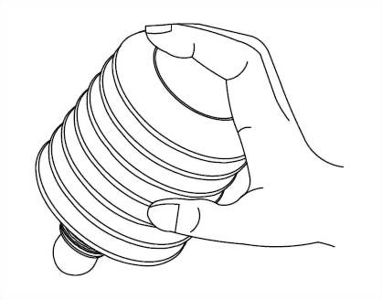
◆ Instruction of Replacing 700cc Grease Cartridge
1
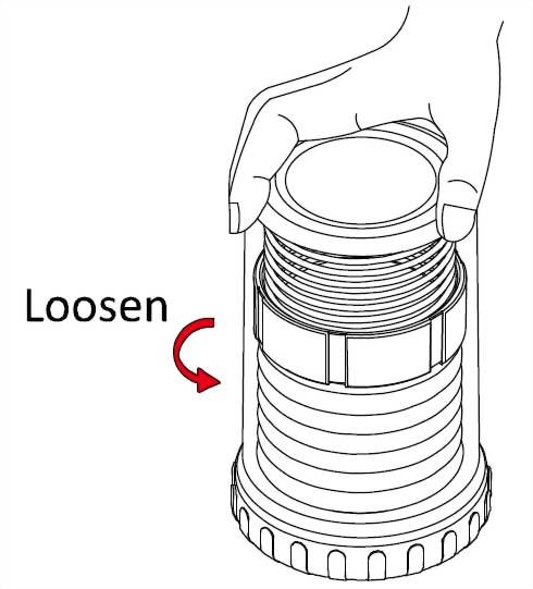
Hold the grease cartridge cover tightly and turn it anticlockwise
to disassemble it from the grease cartridge cover base .
2
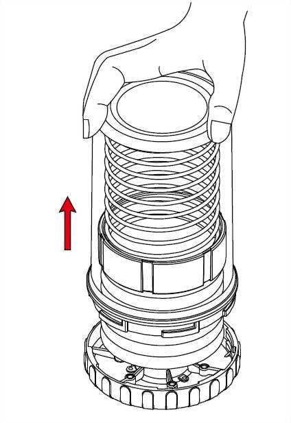
Take the grease cartridge cover out and put it aside.
3

Rotate the used grease
cartridge anticlockwise to remove it from the grease cartridge cover base and dispose of it
properly.
4
Before replacing a new grease cartridge, lightly squeeze out a
little grease in the grease cartridge to prevent air from entering the
lubricator.
5
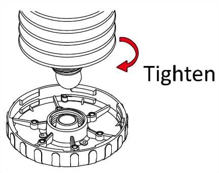
Assemble the new grease cartridge to the grease cartridge cover base by turning it clockwise.
6
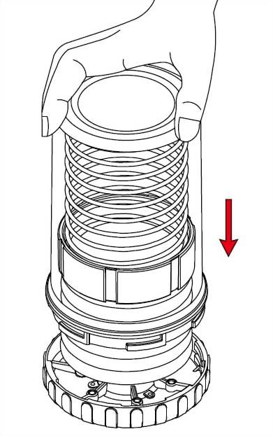
Assemble the grease cartridge cover back to the grease cartridge cover base.
7
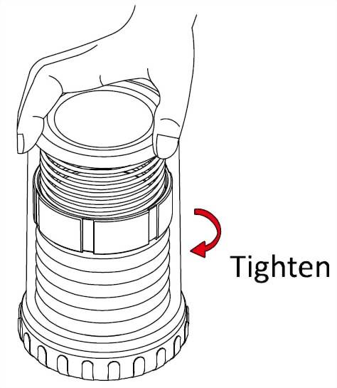
Rotate the grease cartridge cover clockwise to assemble it with the grease cartridge cover base to complete the replacement of the grease cartridge.

")

")


")